Rectifier tapped circuit application coil Diagram wave topperlearning rectifier circuit draw using output junction input diodes waveforms too source Voltage doubler wave circuit half diagram working rectifier capacitor figure
full wave - CircuitLab
Circuit diagram 900w wave seekic
Circuit design
Circuit schematic waveform output circuitlab created usingWaveform generate circuitlab 10+ full wave diagramOutput waveform for this circuit.
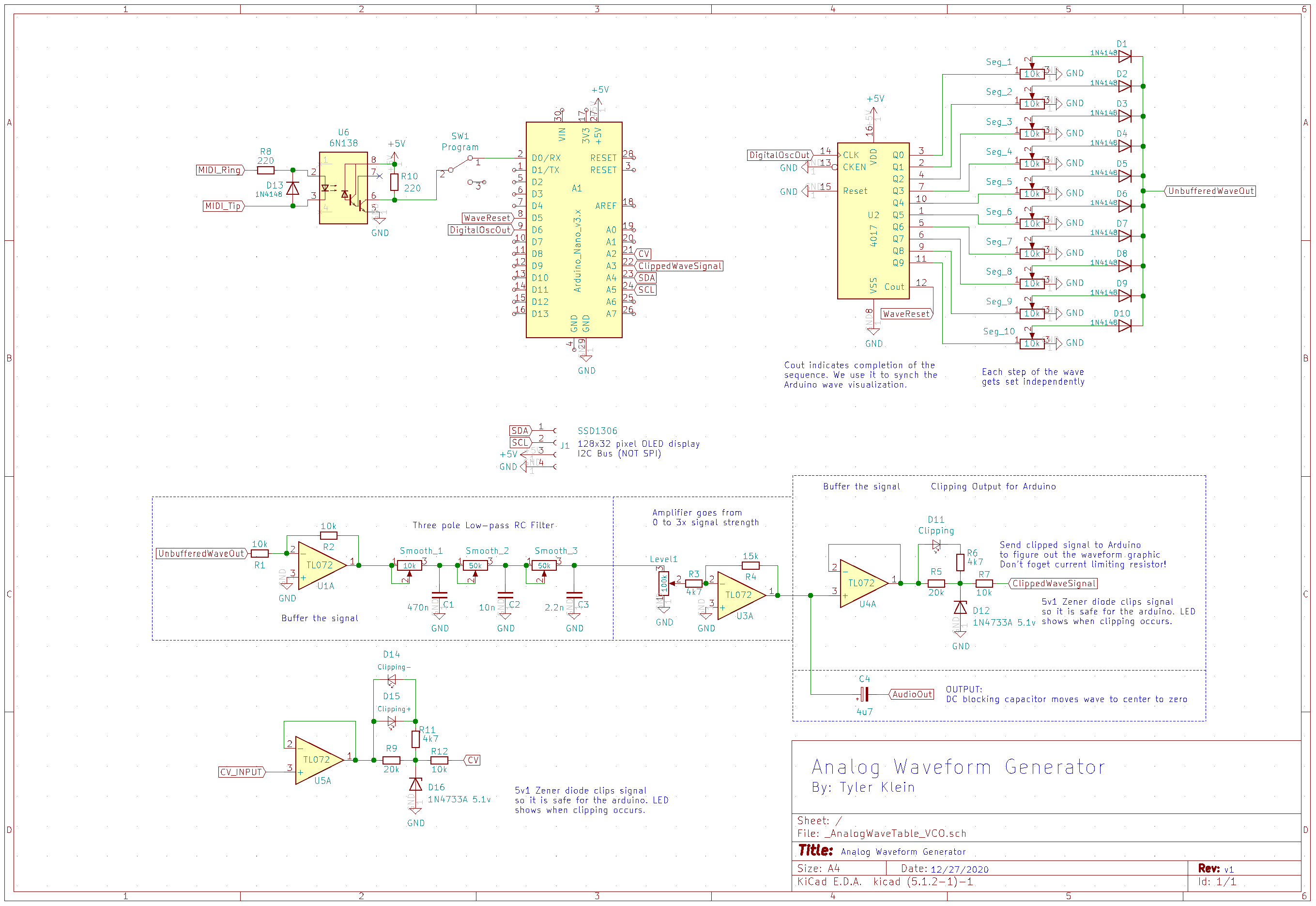
Half-wave & full-wave voltage doubler: working & circuit diagramRectifier waveform labelled waveforms sarthaks Full waveWaveform generator.
![900w full-wave circuit diagram - Basic_Circuit - Circuit Diagram](https://i2.wp.com/www.seekic.com/uploadfile/ic-circuit/s20113224113508.gif)
Center-tapped full-wave rectifier operation -…
Full_wave900w full-wave circuit diagram Circuitlab wave circuit descriptionDraw a labelled circuit diagram of a half wave rectifier and give its.
.
![Half-Wave & Full-Wave Voltage Doubler: Working & Circuit Diagram](https://i2.wp.com/electricalacademia.com/wp-content/uploads/2018/10/17-52.png)
![circuit design - How can you generate this waveform? - Electrical](https://i2.wp.com/i.stack.imgur.com/LLwoO.png)
![Waveform Generator - Things Made Simple](https://i2.wp.com/www.thingsmadesimple.com/wp-content/uploads/2020/12/WaveformGenerator_Schematic.png)
![10+ Full Wave Diagram | Robhosking Diagram](https://i2.wp.com/images.topperlearning.com/topper/questions/14817_image004.gif)
![Center-Tapped Full-Wave Rectifier Operation -… | CircuitBread](https://i2.wp.com/dwma4bz18k1bd.cloudfront.net/tutorials/Center-Tapped-Full-Wave-Rectifier-Typical-Application-Circuit.jpg)
![Output waveform for this circuit - Electrical Engineering Stack Exchange](https://i2.wp.com/i.stack.imgur.com/M6soF.png)